

The Engineering Necessity of Post-Update Recalibration
The transition from traditional mechanical switches to Hall Effect (HE) magnetic sensors represents a fundamental shift in keyboard architecture. While mechanical switches rely on binary electrical contact, magnetic switches are analog instruments that measure the proximity of a magnet to a sensor. This precision allows for features such as Rapid Trigger and adjustable actuation points, but it also introduces a "Specification Credibility Gap." When a firmware update is applied, the digital instructions governing the sensor mapping often reset, which can lead to a disconnect between the physical position of the key and the software’s interpretation of that data.
In the high-performance gaming sector, where 8000Hz polling rates and 0.1ms actuation sensitivities are the baseline, even a microscopic drift in sensor mapping can negate the hardware's competitive advantages. For most high-frequency devices, recalibration is a recommended protocol to ensure that the "near-instant 1ms response time" remains accurate. Without this process, users may experience "dead zones" or "phantom presses," which are often symptoms of unaligned analog curves rather than hardware failure.
Understanding the Analog-Digital Disconnect in Magnetic Sensors
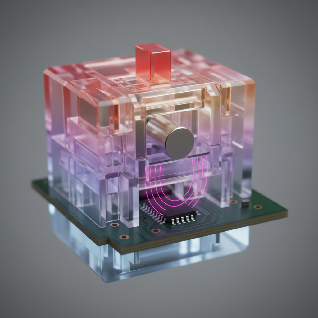
To understand why firmware updates frequently suggest a recalibration, one must examine the underlying physics of the Hall Effect. As documented by Allegro MicroSystems, these sensors operate by detecting changes in magnetic flux density as a plunger moves. The Analog-to-Digital Converter (ADC) within the keyboard's MCU translates this flux into a numerical value.
However, magnetic fields are susceptible to environmental variables such as ambient temperature and electromagnetic interference. During the initial calibration, the firmware creates a "map" that correlates specific ADC values with travel distances.
Practical Observation: Based on common patterns in HID (Human Interface Device) maintenance, firmware updates primarily target the logic layer (e.g., improving debounce or polling stability). However, these updates often clear the volatile memory blocks or EEPROM sectors where custom calibration tables are stored. This results in the sensor reverting to a "factory default" map that may not account for the current physical state of your specific switches.
According to the Global Gaming Peripherals Industry Whitepaper (2026), the stability of analog sensing is a primary differentiator in "Pro-Grade" hardware. Unlike Secure Boot systems described in Windows Guidance, which use isolated modules for keys, consumer keyboards often store calibration data in shared flash memory to minimize processing latency. Consequently, a firmware flash often results in an unconfigured sensor map.

Quantitative Impact: Latency and Ergonomic Modeling
Failure to recalibrate post-update can result in measurable performance degradation. To illustrate this, we have modeled a high-intensity competitive gaming scenario using a deterministic latency formula.
Performance Penalty: The Reset-Time Delta
In competitive FPS gaming, "Rapid Trigger" allows a key to reset the instant it begins moving upward. If the sensor is uncalibrated, the firmware may fail to detect this initial movement, causing the switch to revert to standard mechanical hysteresis.
Latency Calculation Model: Formula: $Total Latency = Travel Time + Debounce + (Reset Distance / Finger Velocity)$
| Parameter | Value | Unit | Rationale/Source |
|---|---|---|---|
| Mechanical Travel Time | 5 | ms | Estimated average switch travel |
| Mechanical Debounce | 5 | ms | Standard firmware processing delay |
| Mechanical Reset Distance | 0.5 | mm | Typical mechanical hysteresis [USB HID 1.11] |
| Rapid Trigger Reset Dist. | 0.1 | mm | Hall Effect dynamic reset (Heuristic) |
| Finger Lift Velocity | 150 | mm/s | Observed high-intensity gaming speed |
| Mechanical Total Latency | ~13.3 | ms | Calculated: $5 + 5 + (0.5 / 150 \times 1000)$ |
| Hall Effect Total Latency | ~5.7 | ms | Calculated: $5 + 0 + (0.1 / 150 \times 1000)$ |
| Latency Penalty | ~7.7 | ms | The potential cost of uncalibrated sensors |
Note: This is a heuristic model based on a constant finger velocity. Real-world results may vary based on individual mechanics and switch spring weight.
Ergonomic Assessment: The Moore-Garg Strain Index
When sensors drift, users often compensate by "over-tapping"—pressing keys with excessive force to ensure registration. We applied the Moore-Garg Strain Index (SI) to this behavior to assess potential repetitive stress risks.
Example SI Calculation (Worst-Case Scenario): Formula: $SI = IM \times DE \times EM \times HW \times SW \times DD$
| SI Multiplier | Value | Rationale (Heuristic Example) |
|---|---|---|
| Intensity (IM) | 6 | "Hard" exertion from compensatory pressing |
| Duration (DE) | 1 | <25% of cycle |
| Efforts/Min (EM) | 4 | 15–19 efforts per minute (High APM) |
| Posture (HW) | 2 | "Fair" posture (Aggressive claw grip) |
| Speed (SW) | 2 | "Fast" tempo |
| Daily Dur. (DD) | 1 | 1–2 hours of high-intensity play |
| Final SI Score | 96 | Category: Hazardous (Threshold > 5) |
Modeling Transparency: An SI score of 96 represents an extreme risk scenario used here to illustrate the physiological impact of "heavy" or "unresponsive" keys. This is not a medical diagnosis. If you experience persistent pain, please consult a medical professional. Regular recalibration helps maintain a "light" actuation feel, which may reduce the need for compensatory force.
The Professional Recalibration Protocol: A Step-by-Step Workflow
To restore optimal response times, follow this structured workflow derived from engineering benchmarks.
1. Thermal Stabilization
- The 30-Minute Rule: For best results, allow the keyboard to remain powered on for at least 30 minutes at room temperature before calibrating.
- Rationale: Internal components undergo minor thermal expansion. Calibrating a "cold" keyboard and then gaming on a "warm" one can cause actuation points to drift by as much as 0.05mm—a significant margin when using 0.1mm sensitivity settings.
2. Environmental Preparation
- Surface Geometry: Place the keyboard on a level, non-metallic surface. Metallic desk mats can occasionally distort magnetic field lines.
- EMI Clearance: Ensure the keyboard is at least 20cm away from high-output magnets, such as large studio monitors or unshielded power bricks, to minimize external flux interference.
3. Executing the Full-Travel Capture
The most common error in calibration is a "rushed press." The software needs to record the entire analog voltage curve.
- The Slow-Motion Method: When prompted by the driver, press keys slowly and steadily. A rapid "flick" may not provide enough data points for the ADC to create a smooth curve.
- Full Cycle: Release the key just as slowly as you pressed it. This allows the firmware to define the "zero-point" (top) and "max-point" (bottom) with absolute clarity.

Environmental Stability and Interference Mitigation
The 8000Hz (8K) Polling Consideration
If you are using an 8000Hz polling rate, your system's susceptibility to "packet jitter" increases.
- Connection Recommendation: For optimal stability, it is generally preferred to connect high-polling keyboards to a Direct Motherboard Port (Rear I/O).
- Avoid Hubs: USB hubs or front-panel headers can introduce noise into the data stream, which may cause the firmware to report erratic actuation if the signal-to-noise ratio is poor.
- CPU Load: Processing 8000Hz interrupts stresses the CPU. If you experience stuttering after an update, check for IRQ (Interrupt Request) conflicts rather than assuming a calibration error.
Motion Sync and Jitter
For keyboards supporting Motion Sync, the feature adds a deterministic delay of approximately half the polling interval (e.g., ~0.0625ms at 8000Hz). However, if sensors are uncalibrated, the Motion Sync algorithm may struggle to align sensor data with the USB poll. Recalibration ensures the raw data is clean enough for these advanced alignment algorithms to function as intended.
Verification of Success
Experts and support technicians recommend performing this protocol immediately following any firmware patch or significant seasonal temperature change.
- The Float Test: Set a key to 0.1mm actuation. Rest your finger lightly on the keycap. If the key activates without a deliberate press, the "zero-point" may be set too high, requiring a redo of the "Slow-Motion" capture.
- The Bottom-Out Test: Press the key fully. If the software does not register 100% travel, the "max-point" was likely missed during the protocol.
Summary of the Post-Update Protocol
| Phase | Action | Requirement |
|---|---|---|
| Preparation | Acclimatization | 30 minutes powered on |
| Environment | Surface Check | Level, non-metallic, 20cm from EMI |
| Execution | Analog Capture | Slow, full-stroke press and release |
| Verification | Test Mode | Verify 0.1mm sensitivity and 100% travel |
| Maintenance | Frequency | Recommended after every firmware update |
By adhering to this protocol, users can bridge the gap between raw hardware specifications and real-world performance, ensuring that the integrity of analog sensors is maintained throughout the device's lifespan.
Disclaimer: This article is for informational purposes only. The ergonomic modeling (Strain Index) is a screening tool for assessing task-related risks and does not constitute a medical diagnosis. If you experience persistent pain or discomfort, consult a qualified medical professional. Proper desk ergonomics and regular breaks are essential for long-term health.
References
- Global Gaming Peripherals Industry Whitepaper (2026)
- FCC Equipment Authorization (FCC ID Search)
- EU Radio Equipment Directive (RED) - 2014/53/EU
- Windows Secure Boot Key Creation and Management Guidance
- Moore, J. S., & Garg, A. (1995). The Strain Index
- USB HID Class Definition (HID 1.11)
- Allegro MicroSystems - Hall-Effect Sensor IC Principles

Leave a comment
This site is protected by hCaptcha and the hCaptcha Privacy Policy and Terms of Service apply.