
The Faraday Challenge: Why Metal Cases Inhibit Wireless Signals
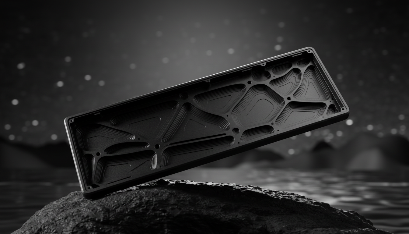
In the pursuit of structural rigidity and premium aesthetics, computer numerical control (CNC) aluminum has become the gold standard for high-performance peripheral enclosures. However, aluminum is a highly conductive material, which creates a physical phenomenon known as a Faraday cage. When a wireless antenna is placed inside a solid metal box, the enclosure effectively blocks electromagnetic radiation, preventing the 2.4GHz or Bluetooth signals from reaching the receiver.
For enthusiasts, this creates a technical paradox: the desire for a "thocky," heavy metal chassis often conflicts with the need for the near-instant 1ms response time required for competitive gaming. To bridge this gap, engineers must treat the metal case not as a solid barrier, but as a complex RF (Radio Frequency) environment that requires precise "windows" or apertures to allow signal propagation.
According to the FCC OET Knowledge Database (KDB), maintaining signal integrity while meeting strict emission standards is a primary hurdle for wireless devices in metallic enclosures. Successfully integrating these features requires a deep understanding of waveguide physics, material science, and antenna placement heuristics.

Engineering the Wireless Window: Aperture Design and Material Selection
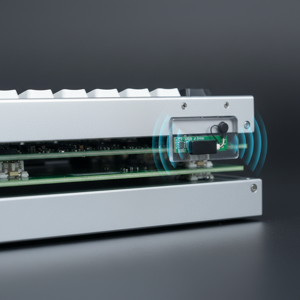
The most effective solution for maintaining connectivity in a metal chassis is the integration of an RF-transparent "window." This is typically a CNC-machined cutout in the aluminum frame, backfilled with a dielectric material such as plastic or glass. However, an aperture is not a simple hole; in a 3D CNC enclosure, it acts as a waveguide-coupled cavity.
Dielectric Loading and Attenuation
The material used for the window significantly impacts the signal. Every material has a dielectric constant ($\varepsilon_r$), which affects the velocity and wavelength of the radio waves passing through it. Common choices include Polycarbonate ($\varepsilon_r \approx 2.9$) and ABS ($\varepsilon_r \approx 2.4-4.1$).
A critical engineering rule of thumb is to keep the window thickness under 2mm. Research into Diversity Performance and Antenna Placement indicates that transparent polycarbonate thicker than 3mm can attenuate 2.4GHz signals more than anticipated, shifting the antenna's resonant frequency and causing a downward frequency shift of up to 3-5%.
Modeling Note: Wireless Window Attenuation
Parameter Typical Value Unit Rationale Window Material Polycarbonate N/A High impact resistance and RF transparency Material Thickness 1.5 - 2.0 mm Balance of structural integrity and minimal loss Dielectric Constant ($\varepsilon_r$) 2.9 Ratio Standard for PC; affects resonant frequency Frequency Shift 3 - 5 % Estimated shift due to dielectric loading Target Band 2.4 - 2.48 GHz Standard ISM band for gaming peripherals This model assumes a standard 2.4GHz dipole antenna setup. Real-world results may vary based on exact material purity and internal cavity geometry.
The Risk of Parasitic Antennas
A common manufacturing pitfall involves the CNC machining process itself. If the edges of the metal cutout are not perfectly smooth, microscopic conductive burrs can remain. These burrs can act as parasitic antennas, coupling RF energy and re-radiating it in unpredictable patterns. This can degrade shielding effectiveness by 10-20 dB. To mitigate this, premium builds often utilize electropolishing or micro-abrasive blasting to ensure a clean RF exit path.
Antenna Placement and PCB "Keep-Out" Zones
The physical location of the antenna module relative to the metal chassis and the plastic window is the most frequent failure point in wireless metal keyboards. Signal strength is not just about having a hole in the case; it is about the "line of sight" between the antenna and the external environment.
The 5mm Rule
Empirical analysis derived from engineering troubleshooting shows that placing the antenna module less than 5mm from the interior surface of the plastic window typically yields a 3-5dB improvement in signal strength. If the antenna is buried too deep within the metal cavity, internal resonances can create gain variations exceeding 15dB, leading to "dead zones" where the connection drops despite the user being close to the receiver.
PCB Grounding and Interference
On the PCB level, engineers must define a "keep-out" area. This is a section of the circuit board where no copper ground planes, traces, or components are present. Ground planes are essential for electrical stability, but if they are too close to the antenna, they act as a sink for RF energy, severely limiting the broadcast range. For tri-mode devices that include Bluetooth—which is more susceptible to interference than 2.4GHz—a larger keep-out area or a dedicated secondary antenna location is often required to maintain a stable connection.
According to the Bluetooth SIG Launch Studio, proper implementation of these antenna layouts is vital for passing qualification and ensuring interoperability across different host devices.
The 8000Hz (8K) Polling Rate: Wireless Physics and System Limits
As the industry moves toward 8000Hz polling rates to achieve ultra-low latency, the engineering challenges in metal cases intensify. High polling rates require massive amounts of data to be transmitted with extreme precision, leaving almost no room for packet loss or signal jitter.
The Math of 8K Latency
To understand the stakes, we must look at the timing intervals:
- 1000Hz: 1.0ms interval.
- 4000Hz: 0.25ms interval.
- 8000Hz: 0.125ms interval.
At 8000Hz, the system must process an interrupt every 0.125ms. If the metal case causes even minor signal attenuation, the resulting packet loss can lead to "stuttering" that is visually perceptible on high-refresh-rate monitors (240Hz+). Furthermore, features like Motion Sync must be recalibrated; at 8K, the deterministic delay added by Motion Sync is approximately 0.0625ms, which is negligible compared to the ~0.5ms delay at 1000Hz.
Sensor Saturation and Movement
To fully utilize an 8000Hz bandwidth, the mouse sensor must generate enough data points. This is governed by the formula: Packets = Movement Speed (IPS) × DPI. For example, to saturate the 8K bandwidth at 800 DPI, a user must move at least 10 IPS. However, at 1600 DPI, the required speed drops to 5 IPS. In a metal-shielded environment, maintaining this data flow requires a high-gain antenna setup to ensure no packets are dropped during micro-adjustments.
CPU and USB Topology Constraints
The bottleneck for 8K wireless performance is often the host computer's IRQ (Interrupt Request) processing. 8000Hz polling puts a significant load on a single CPU core. For optimal performance, wireless receivers must be plugged into Direct Motherboard Ports (Rear I/O). Using USB hubs or front-panel headers introduces shared bandwidth and potential interference, which, when combined with the attenuation of a metal keyboard case, can cause latency variance to exceed the ±0.5ms stability threshold.
For a deeper dive into these standards, refer to the Global Gaming Peripherals Industry Whitepaper (2026).
Global Compliance and Safety Standards
Integrating wireless technology into metal enclosures is not just a performance challenge; it is a regulatory one. Manufacturers must ensure that their devices meet global standards for RF exposure and electromagnetic compatibility (EMC).
Regulatory Frameworks
- FCC (USA): Devices must comply with Part 15 of the FCC rules. The metal case acts as a shield, which can actually help pass unintended emission tests but makes intentional radiator (antenna) testing more complex.
- RED (European Union): The Radio Equipment Directive (2014/53/EU) requires rigorous testing of receiver performance and efficient use of the radio spectrum.
- ISED (Canada): Similar to the FCC, the ISED Canada Radio Equipment List (REL) tracks certified devices to ensure they do not interfere with other licensed services.
Battery Safety in CNC Cases
Because CNC metal cases are rigid and non-flexible, battery safety is paramount. If a lithium-ion battery swells inside a solid aluminum enclosure, the lack of expansion room can lead to structural failure or a thermal event. High-quality builds adhere to UNECE UN 38.3 for battery transport safety and utilize internal brackets to prevent the battery from contacting sharp CNC-machined edges.
Optimizing the Wireless Metal Experience
For the performance-focused enthusiast, a CNC metal keyboard represents the pinnacle of build quality. By understanding the engineering behind "Wireless Windows," users can make informed decisions and troubleshoot connectivity issues effectively.
Key Takeaways for Maximum Stability:
- Line of Sight: Ensure the wireless receiver is within 10 meters and has a clear path to the keyboard's RF window.
- USB Placement: Always use rear motherboard USB ports for high-polling (4K/8K) receivers to avoid IRQ conflicts.
- Firmware Updates: Manufacturers often release firmware updates to tune the antenna gain or adjust sleep timers, which can significantly improve stability in high-interference environments.
- Avoid Thick Barriers: Placing a metal keyboard behind a monitor or inside a desk drawer will exacerbate the Faraday cage effect.
By treating the metal chassis as an integrated part of the RF system rather than an obstacle, engineers can deliver the tactile perfection of CNC aluminum without sacrificing the freedom of wireless performance.
Disclaimer: This article is for informational purposes only. Modifying the internal structure or antenna placement of a wireless device may void your warranty and could potentially violate local RF regulations. Always consult with the manufacturer before performing internal modifications.

Hinterlasse einen Kommentar
Diese Website ist durch hCaptcha geschützt und es gelten die allgemeinen Geschäftsbedingungen und Datenschutzbestimmungen von hCaptcha.