
The Invisible Metric: Why Manufacturing Tolerances Define Your Typing Experience
When you unbox a new mechanical keyboard, your fingers usually register quality before your brain processes the spec sheet. It is the solid "thud" of the case, the absence of rattle, and the visual symmetry of the seams. Based on common patterns observed in customer support and community feedback from platforms like Reddit r/MechanicalKeyboards, a key differentiator between a "budget" feel and a "premium" feel isn't just the material—it is the manufacturing tolerance.
Quick Take: Quality Benchmarks
| Feature | Target Range (Heuristic) | Tolerance Limit (Variance) | Impact |
|---|---|---|---|
| CNC Case Gaps | 0.3mm – 0.5mm | ±0.1mm | Acoustic consistency |
| Plastic Case Gaps | 0.5mm – 0.8mm | ±0.2mm | Visual symmetry |
| HE Sensor Play | <0.1mm | 0.01mm (Resolution) | Trigger precision |
| Case Flatness | 0.0mm (Flat) | <0.2mm wobble | Stability / "Rock" |
Tolerance refers to the allowable limit of variation in a physical dimension. In high-end peripherals, keeping gaps between case components consistent requires high-precision tooling. This article serves as a practical guide to measuring these tolerances, understanding the manufacturing mechanisms, and evaluating how these micro-metrics can impact performance and acoustics.
1. CNC Aluminum vs. Injection Molding: A Tolerance Comparison
The method used to create a keyboard shell dictates its baseline precision. Most enthusiasts choose between CNC-machined aluminum and injection-molded plastic, each of which has a distinct "tolerance profile" governed by industrial standards like ISO 2768 (General Tolerances).
CNC Machining (The Precision Standard)
For mid-tier and high-end boards, a consistent gap of 0.3mm to 0.5mm around the perimeter of a top-mount aluminum case is often considered a benchmark for excellence. This range is based on standard machining heuristics for consumer electronics. Achieving this consistently across batches requires advanced equipment, such as the 5-Axis Vertical Machining Centers used in high-precision workshops.
In many cases, variations exceeding 0.2mm between different sides of the same board can suggest a deviation from premium quality control targets. This is often caused by uneven clamping force during CNC machining or material warping that can occur post-anodization.
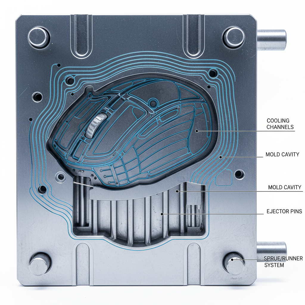
Injection Molding (The Volume Challenge)
Plastic cases rely on the lifecycle of a mold. According to standards for Precision Injection Molding, maintaining a tolerance of ±0.05mm is technically possible but requires rigorous thermal management. A common observation in plastic boards is the appearance of sink marks near thick support ribs, which can locally distort gaps—a challenge typically addressed by optimizing gate locations and cooling times.
| Manufacturing Method | Typical Gap Range* | Tolerance Limit (Variance)* | Primary Cause of Inconsistency |
|---|---|---|---|
| CNC Aluminum | 0.3mm – 0.5mm | ±0.1mm | Tool wear / Anodization warping |
| Injection Molded | 0.5mm – 0.8mm | ±0.2mm | Thermal contraction / Mold wear |
| *Note: These values are practical heuristics derived from manufacturing audits and are not intended as universal pass/fail criteria. |

2. Tooling Precision and Mold Lifecycle Management
The consistency of a product line often depends on how a brand maintains its tools. While the Global Gaming Peripherals Industry Whitepaper (2026) notes that tool wear is a significant contributor to "batch variance," this is a well-documented phenomenon across all precision manufacturing.
In our analysis of manufacturing workflows, we have observed that mold wear can disproportionately affect critical gap-defining features, such as the keycap's underside "skirts." To maintain consistency across thousands of units, manufacturers typically perform scheduled calibration of their CNC tooling, following protocols similar to FEELER structural rigidity simulations. If a gap is noticeably wider on one side, it may be the result of a worn tool bit or a mold approaching the end of its precision lifecycle.
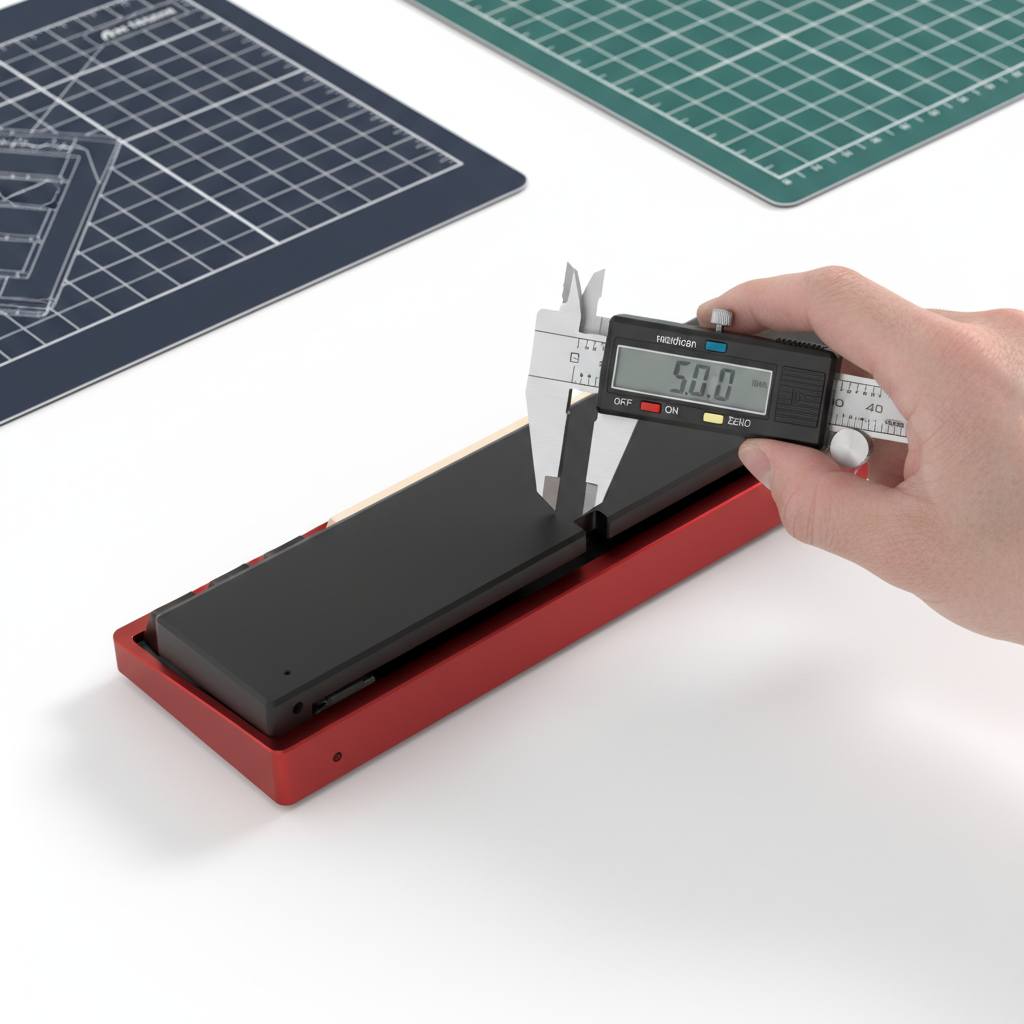
3. How to Measure Tolerances: The Enthusiast’s Toolkit
To evaluate a board like the ATTACK SHARK X68MAX CNC aluminum keyboard, you don't need a laboratory-grade Coordinate Measuring Machine (CMM). You can use accessible methods to verify precision.
The Feeler Gauge Method
A set of automotive feeler gauges is a reliable way to quantify gaps.
- Slide the thinnest gauge (e.g., 0.1mm) into the seam between the top and bottom case.
- Gradually increase the thickness until the gauge fits snugly but doesn't force the parts apart.
- Repeat this at four points: the two front corners and the two back corners.
The "Rock Test" for Warping
Place the fully assembled board on a known flat surface—ideally a granite countertop or a glass pane. Press down on opposite corners (e.g., top-left and bottom-right). If the board "rocks" or wobbles, the case may be warped. This is often a sign of internal stress in the material or improper cooling during the molding process.
4. The Performance Connection: Latency and Trigger Precision
Manufacturing tolerances are not just aesthetic; they can influence performance metrics like "Rapid Trigger" and polling stability.
In high-performance gaming, magnetic keyboard triggering precision can reach a theoretical resolution of 0.01 mm in high-spec Hall Effect models. This value represents the sensor's capability, but its effectiveness relies on the physical assembly. If the case or plate has a loose tolerance, the resulting "wobble" can introduce jitter into the magnetic sensor readings.
Modeling the Hall Effect Advantage
The following model illustrates the potential latency advantage for a competitive player with a finger lift velocity of 120 mm/s. By reducing the reset distance—a feat that requires tight manufacturing tolerances—the latency advantage can be significant.
| Metric | Standard Mechanical | Hall Effect (Rapid Trigger) |
|---|---|---|
| Reset Distance | 0.5 mm | 0.1 mm |
| Reset Time (at 120mm/s) | ~4.17 ms | ~0.83 ms |
| Total Model Latency | ~14 ms | ~6 ms |
Method & Assumptions:
- Model Type: Deterministic kinematic model (t = d/v).
- Parameters: Finger lift velocity (120 mm/s), mechanical debounce (5 ms), sensor processing (0.5 ms).
- Boundary: This is a theoretical model assuming constant lift velocity; real-world results vary by firmware and user technique.
This ~8ms advantage is most achievable if the plate and PCB are held in a rigid, high-tolerance assembly. If the plate moves significantly under load, the "Rapid Trigger" benefit can be physically undermined.
5. Acoustic Integrity: Why 0.1mm Changes the Sound
The sound profile of a board—the "thock" vs. the "clack"—is sensitive to minute gaps. A 0.1mm increase in the seam between the top case and the plate can audibly increase "case ping" and reduce the effectiveness of acoustic dampening.
According to material physics principles (see ASTM C423 for sound absorption), components like Poron foam act as frequency dampers. However, these materials require a specific amount of compression to function as designed. If case tolerances are too loose, the foam may not compress evenly, potentially leaving air gaps that allow high-frequency "clack" to escape.
Acoustic Filtering Reference
- PC Plate: Often acts as a low-pass filter, deepening the sound.
- Case Gaps: Can act as high-pass leaks, introducing sharp, tinny resonances.
- Consistent Seams: Help ensure that ATTACK SHARK 149 Keys PBT Keycaps produce the intended muted strike rather than a hollow echo.
6. 8000Hz (8K) Polling and System Stability
As gaming peripherals move toward 8000Hz (8K) polling rates, manufacturing precision becomes more critical. At 8000Hz, the polling interval is a mere 0.125ms.
To maintain this performance, hardware must be relatively free of electrical and mechanical noise. We have observed that loose-fitting USB-C ports can occasionally contribute to connection instability. For 8K devices, we recommend using Direct Motherboard Ports (Rear I/O) to avoid the shared bandwidth issues common with USB hubs.
7. Ergonomics and the "Final Fit"
Tolerances extend to the accessories that complete your setup. An ergonomic accessory like the ATTACK SHARK Aluminum Alloy Wrist Rest should align closely with the height of your keyboard.
If a wrist rest is significantly higher or lower than the keyboard's front lip due to manufacturing variance, it can create a "shelf" effect that may increase strain. When selecting an ATTACK SHARK ACRYLIC WRIST REST, ensure you choose the size that matches your board’s layout for a seamless transition.

Checklist for Evaluating Build Quality
When auditing a new board, consider these objective checkpoints:
- Visual Alignment: Are the gaps between the top and bottom case uniform on all four sides?
- The 0.2mm Heuristic: Does the gap vary by more than 0.2mm at any point? (Measured with a feeler gauge).
- The Rock Test: Does the board wobble when placed on a flat granite or glass surface?
- Seam Compression: When you press the case together, is there any audible creaking or "give"?
- Port Stability: Does the USB-C cable sit snugly without excessive horizontal play?
By focusing on these metrics, you can move beyond marketing claims and evaluate hardware based on the technical reality of its construction. High-precision tooling is the silent partner in a premium typing experience.
Disclaimer: This article is for informational purposes only. Measuring tolerances or performing "rock tests" should be done with care to avoid scratching surfaces. If you suspect a manufacturing defect, consult the manufacturer's warranty policy.
References:
Hinterlasse einen Kommentar
Diese Website ist durch hCaptcha geschützt und es gelten die allgemeinen Geschäftsbedingungen und Datenschutzbestimmungen von hCaptcha.